在前面的文章中,演示了如何通过GPIO的高低电平控制LED灯的亮起和熄灭,这篇文章介绍如何联动人体红外传感器来控制LED小灯的亮起和熄灭。
HC-SR501人体红外感应传感器
HC-SR501长下图这样,圆形的球是菲涅尔透镜.:
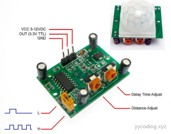
有三个插脚,VCC接树莓派5V电源接口, GND接树莓派GND接口,OUT是输出接口,接树莓派的GPIO口,感应到人体后,输出高电平,否则输出低电平。有两种信号输出模式
- L不可重复,表示感应输出高电平后,延时时间一结束,输出将自动从高电平变为低电平。
- H可重复,表示感应输出高电平后,在延时时间段内,如果有人体在其感应范围内活动,输出将一直保持高电平,知道人离开后才延时将高电平变为低电平。
调节方式就是上图左下角的黄色跳线,拔下就可以选择H或者L,默认为H。
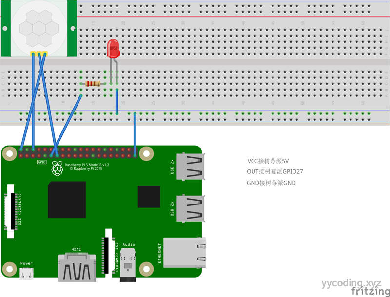
这里由于传感器会向树莓派插口输出电压,尤其要注意的是,有些传感器比如超声波测速传感器输出的电压是5V,如果直接连在树莓派的插脚上,树莓派只能接受大概3.3V的电压,直连可能会烧坏树莓派,所以需要连电阻,这里输出的电压是3.3V,所以直连即可。
接线图如下,保留了上篇文章里LED小灯的接线:
写代码
首先我们新建一个HC-SR501类,用来封装传感器;
public class HCSR501 : IDisposable
{
    public GpioController controller;
    public readonly int outPin;

    public HCSR501(int _outPin, PinNumberingScheme pinNumberScheme = PinNumberingScheme.Logical)
    {
        outPin = _outPin;
        controller = new GpioController(pinNumberScheme);
        controller.OpenPin(outPin, PinMode.Input);
    }

    public bool IsMotionDetected => controller.Read(outPin) == PinValue.High;
    public void Dispose()
    {
        controller?.Dispose();
        controller = null;
    }
}
在上述类中,构造函数接受输出口连接树莓派的GPIO编号,Pin口编码方式为逻辑编码。因为树莓派插口有很多种编码方式,如下图,以数字1,2,3表示的是板载编码,旁边的以GPIO开头的就是逻辑编码。比如3代表的板载编码对应的就是GPIO2逻辑编码,在这里就直接输入2即可:

在构造函数中,首先打开Pin端口,同时定义端口的方式为输出,因为这个传感器是输出信号型的。
接着在IsMotionDetected属性中,读取Pin端口的输出,如果是高电平,则表示探测到运动。
最后在Main主函数中,当探测到人体运动时,点亮LED小灯。
static void Main(string[] args)
{
    int ledPin = 17;
    int hcsr501Pin = 27;
    Console.WriteLine("Hello PIRLight!");
    using (GpioController ledController = new GpioController(PinNumberingScheme.Logical))
    {
        using (HCSR501 sensor = new HCSR501(hcsr501Pin))
        {
            ledController.OpenPin(ledPin, PinMode.Output);
            while (true)
            {
                if (sensor.IsMotionDetected)
                {
                    ledController.Write(ledPin, PinValue.High);
                    Console.WriteLine("Detected Human! Turn the Led on");
                }
                else
                {
                    ledController.Write(ledPin, PinValue.Low);
                    Console.WriteLine("Undetected Human! Turn the Led off");
                }
                Thread.Sleep(1000);
            }
        }
    }
}
效果如下: